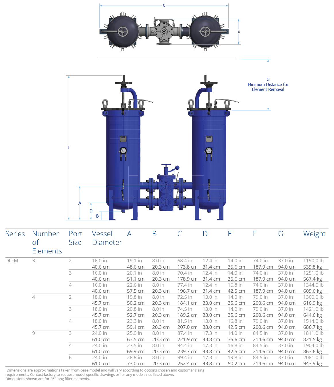
DLF-M Low Pressure High Flow Duplex Filter Assembly

Designed to maintain continuous filtration, even throughout element servicing, the DLF series filter assemblies provide two high efficiency, high capacity filter housings coupled by a user-friendly 6-way, 3 position valve that completely seals the system from the atmosphere. Use the DLF(M) to remove particulate and water from a variety of fluids and maximize your uptime.

Ideal for systems where filters must be serviced without system interruption such as hydraulic, gearbox, pulp and paper, rolling mill oil, bulk oil handling, and high flow return-line filtration.

Max Operating Pressure: 150 psi (10 bar)

Available options up to 450 psi (31 bar)


Download Brochure

Operating Temperature

Fluid Temperature

30°F to 225°F

(0°C to 105°C)

Ambient Temperature

-4°F to 140°F

(-20C to 60C)

Operating Pressure

150 psi (10.3 bar) standard. See special options for additional pressure ratings.

Element Collapse Rating

HP105

150 psi (10.3 bar)

HP106

150 psi (10.3 bar)

HP107

150 psi (10.3 bar)

HP8314 (All Codes)

150 psi (10.3 bar)

PUT STUFF HERE
integral Element Bypass Setting

HP106

25 psid (1.7 bard)

HP107

50 psid (3.4 bard)

HP8314 (Code 82)

25 psid (1.7 bard)

HP8314 (Code 83)

50 psid (3.4 bard)

Materials of Construction

Housing

Industrial coated carbon steel
 Media Description

M

G8 Dualglass, our latest generation of DFE rated, high performance glass media for all hydraulic & lubrication fluids. βx[C] ≥ 4000

A

G8 Dualglass high performance media combined with water removal scrim. βx[C] ≥ 4000

W

Stainless steel wire mesh media βx[C] ≥ 2 (βx ≥ 2)

Fluid Compatibility

Petroleum and mineral based fluids, #2 diesel fuels (standard). For specified synthetics contact factory for compatibility with fluorocarbon seal option. For phosphate ester or skydrol fluid compatibility select fluid compatibility from special options.

Replacement Elements
DLF replacement elements
ΔP Factor
DLF ΔP factor chart
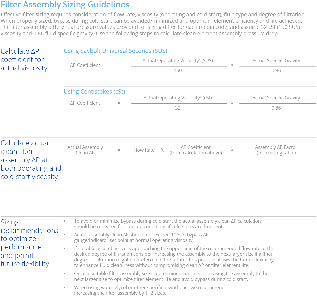
Max flow rates and ΔP factors assume υ = 150 SUS, 32 cSt. See filter assembly sizing guideline for viscosity conversion formula on page 22 for viscosity change.
Filter Sizing Chart
DLF filter sizing chart
Max flow rates and ΔP factors assume υ = 150 SUS, 32 cSt. See filter assembly sizing guideline for viscosity conversion formula on page 22 for viscosity change.